EtherLynx Hardware
EtherLynx System Basic Components

Not shown: Start sensor cable, Ethernet cables, USB-Serial adapter, mounting hardware and computer. |
|
With the EtherLynx camera system, the timing circuitry - if enabled - is contained in the camera. The EtherLynx camera is linked by means of an Ethernet connection to the primary computer and - if one is being used - to the network of evaluation and data management computers. It is possible to connect as many cameras as needed to the network.
If one camera in a networked EtherLynx system is equipped with the timing circuitry, and it is powered on, then all cameras on the network will produce time-indexed images – whether or not the timer enabled camera is being used to capture image. This means that adding a second or subsequent camera to an FAT system can be very affordable.
The EtherLynx range of cameras should be covered if rain is a threat. They require AC power or Power over Ethernet (PoE), and can be fitted with a number of different lens mounts including: CS-mount, C-mount and F-mount (Nikon). Depending on the lens in use, remote controlled zoom, focus and iris are available.
Current generation EtherLynx Vision-Series cameras are shipped with a CS-mount and a CS to C-mount adapter.
All cameras can also incorporate an optional physical or electronic viewfinder so the operator can look through the lens of the camera for alignment and focusing purposes.
EtherLynx Vision cameras come standard with a 8-48mm CS-mount lens with remote controlled zoom, focus and iris. In addition, a manual 6mm C-mount lens is provided for installations very close to the finish line.
EtherLynx Vision PRO cameras come standard with a 12.5-75mm C-mount lens with remote controlled zoom, focus and iris. In addition, a 2.8-10mm CS-mount lens is provided for installations very close to the finish line.
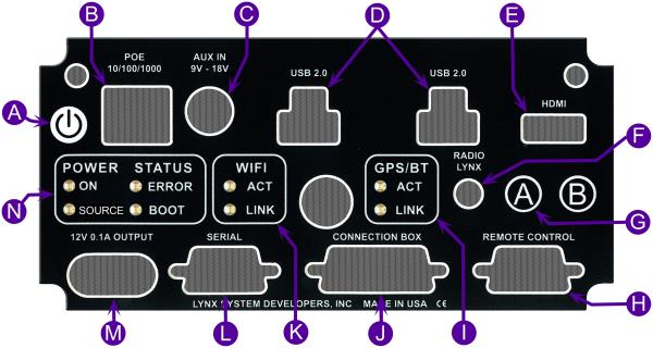
| A |
Power button
|
| B |
Gigabit Ethernet connection
|
| C |
AUX power connection
|
| D |
USB 2.0 ports
|
| E |
HDMI output port
|
| F |
|
| G |
Electronic ViewFinder mode toggle button
|
| H |
Remote Lens/Positioner port |
| I |
Internal GPS indicator |
| J |
Connection Box port |
| K |
Wi-Fi port (not in use) |
| L | 12 volt output |
| M |
Power & Status indicators
|
The Connection Box is used to connect various external devices, such as
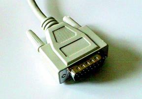
The DB15 connectors on the ends of the Connection Box cable are connected between the back of the Camera and the Connection Box.
DB15 Connector

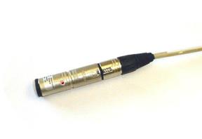
The FinishLynx Start Sensor detects the changes in air pressure caused by the firing of the gun and sends a signal to the computer. FinishLynx will operate with a variety of start signal generators.
The standard Lynx Start Sensor is a 3” long round metal case with an XLR (three-pronged) connector on one end and an LED (light emitting diode) which is visible through the hole in the side of the sensor body. These sensors are of the normally closed type and this is the default setting.
Normally Open means that the sensor is a switch that closes when a start is detected. This is like a light being off in a room and going on when the start is detected. Normally Closed means that the sensor is a switch that opens when a start is detected. This is like a light being on in a room and going out when the start is detected. The advantage of a normally closed set up is that the software can monitor to check that the Start Sensor is still connected.
The Start Sensor is connected to the XLR (three-pronged) connector on the Connection Box labeled “Start” with the Start Signal cable provided.
Start Sensor

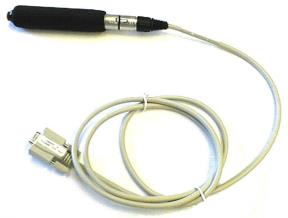
The Capture Button is used to trigger the EtherLynx camera into action, transferring the photo-finish image to the FinishLynx software. It needs to be connected directly to a serial port or a USB port on the computer with the USB-Serial adapter supplied.
Capture Button and Cable


